
The extension PCB
The extension board is made of normal 1,6mm thick FR4-PCB. The normal board-size is about 91x91mm, but I have chosen to use 75x80mm. Then one don't have to saw anything extra to fit the connector and it is possible to get two boards from one 100x160 standard PCB. The layout is simple and you find it as a CorelDRAW-file here.
The intention with this board is to be able to adjust and maintain the front-end board more easily, if you are up to build a new front-end take a look here.
If you will try to build a new SSB-IF unit, or similar, you will have to make different types of extension-boards, since some of the FT225-boards are double sided. The layout for this extension-board is single-sided, but the PCB should be double sided. One side will have the layout and the other side will only have a ground-plane, ie connected to ground. This will give better high-frequency performance.
Take care when you make your PCB. If you have not worked with acids before, have somebody to help you!
The connector
I have used a connector made by Compar. The distance between the connectors is 3,96mm, ie not the more common distance of 2,54mm. The connector has 18 pins and you find the pinout here.
In Sweden this connector is obtainable from Elfa and has the order-number 43-758-46 or 43-757-54. Unfortunately these connectors are both the single-sided type. It will work but the double-sided type is better if you like a more reliable solution. Elfa does not have the double-sided type any longer.
NB! If you use the type mentioned above, take care when fitting the FT225-pcbs since one have to leave about 1mm at each side when connected! If not there are potential risk for shortcircuit!
I am sure that there are several other manufacturers making this type of connector and there are probably plenty of connectors available in junk-boxes!
The layout
I did not bother to have the tracks with an impedance of 50 ohm since my font-end does have a separate SMB-connector for the received 144MHz-signal. If one would like to have them with any special impedance it is very easy to find this in some book.
(The width should be about 3,1mm to get a 50 ohm impedance with a 1,6mm thick FR4-PCB.)
Since the connector used in the FT225 for the front-end is a single sided type, the ground-plane can't go all the way down to the connector. This would shorten all connections! There are two ways of fixing this, depending on what method is used when making the board. If you do not buy PCBs with UV-sensitive film you have to put, before the etching, some kind of tape on the surface but not at the connector. If you are using PCBs with UV-sensitive film, you just cut the cover-film with a sharp knife and remove the cover-film were the connector would be. Now it will be easy to remove the sensitive UV-film with acetone or similar.
Ground connections
On several places one should make good contact between the ground-plane and the layout-side of the PCB. These connections could be made of normal wire the important thing is that there must be plenty of them! Unfortunately these ground connections will also mean that you might not be able to use the same extension board for all FT225-boards! Check with the schematics before you use this extension-board with any other board than the front-end!
The ground connections are most important at the tracks beside the LO-signal, number 17. (Both number 16 and 18 are grounded as you can see on the pinout.)
Alternative solution
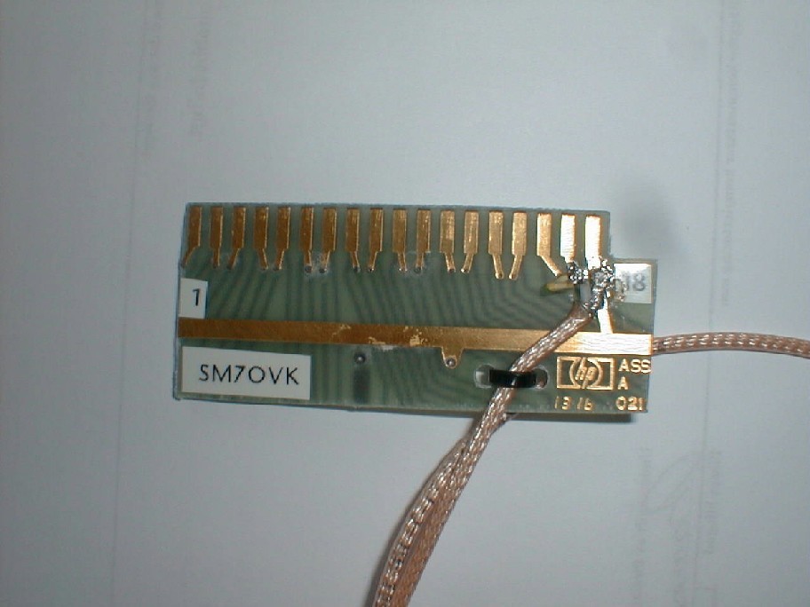
Another way to get a connection, if you only want to get one or two signals to or from the FT225RD, is to take an existing board and cut off the connector, see picture.
I found this connector on a memory-card from a known instrument-maker. This connector is gold-plated and it's easy to connect, as in this case, a coaxialcable. The board is ready in a few seconds. With this simple board it's possible, with the front-end removed, to make measurements on the local-oscillator.