Beginning
In some way this page "disappeared" from my computer and from the server... I can't say anything, but I really do not know what happened. I have tried to "restore" this file as I remember it, but I'm also sure that it's not 100% complete. If somebody managed to download this file before it disappeared, please send it to me!
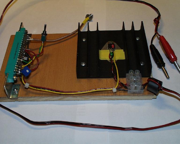
In the beginning I had ideas of making a special test-PCB. I changed my mind and I have made a small "test-jig" instead. The reason is of course to keep everything as simple as possible!
The test-jig is made of some wood holding the 18-pin Compar-connector. In this way it's easy to make measurement on the circuit and I also have switches and potentiometers to play around with.
You can see the result in action here with a totally unmodified front-end.
"Construction"
The idea is just to be able to connect the front-end to a power-supply and possibilities for measurements. An advantage with a direct connection between the rear antenna connector and the front-end is that it's better when adjusting the front-end, there is no influence of any extensionboard.
Mechanics
The Compar-connector is held by two pieces of aluminium, these originates from an old circulator from an old base-station for mobile-telephone...
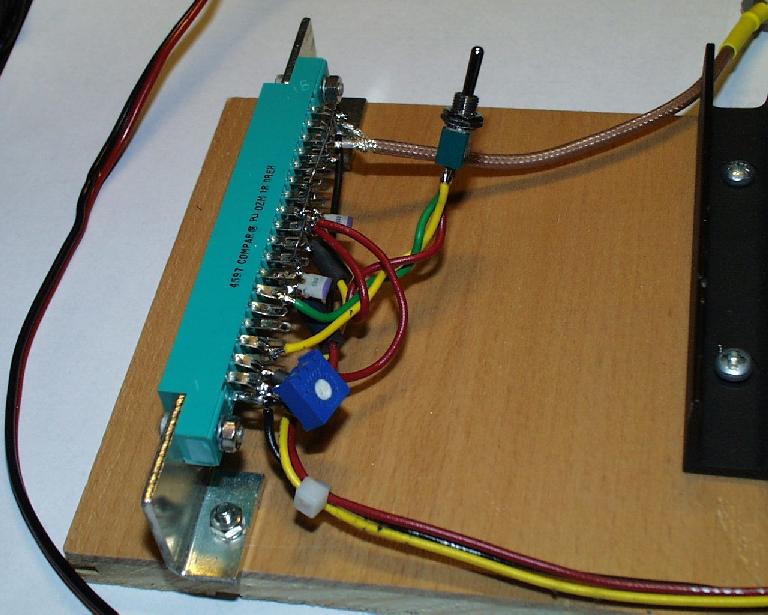
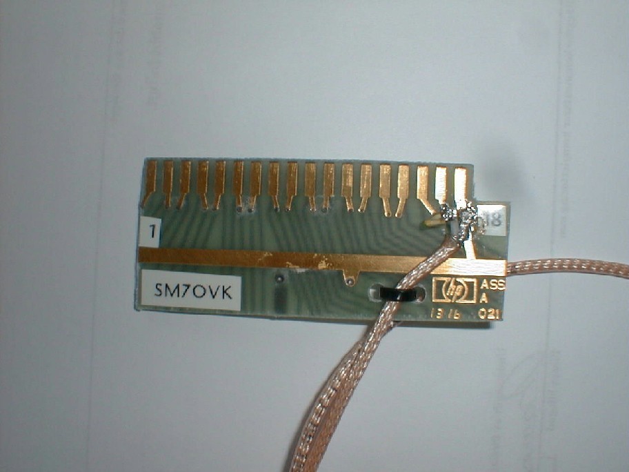
Two M3-screws keep the connector in place. It's easy to see on a close up.
Power supply
I feed the test-jig with 13.6VDC. The incoming DC-source is filtered with a small ferrite toroid. I don't know how effective this is, and I don't think that one must have a ferrite, but I usually place them with some turns of the DC-cable before all radios or accessories. I don't know anything about the ferrite that is used but the type is found on cables for PC-equipment and they must do something good... A big difference compared with PC-equipment is that PC-equipment normally only have a half turn, ie the cable just go trough the ferrite and I use at least two turns! (This increases the inductance with about 16 times.)
With an ordinary regulator, 7808, I get an 8VDC source. It's important to mount some small capacitors very close to the voltage regulator! (I have seen these little fellows oscillating on several hundred MHz or a couple of GHz... and we certainly don't want to feed the PCB under test with any strange signals that could ruin the measurement!)
All ground-connections are put together on the Compar-connector. The local-oscillator is connected with a short coaxial-cable with a SMA-connector, (it could as well be a BNC-connector - but this was what I had.)
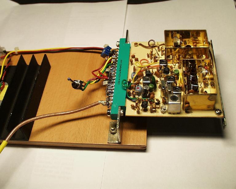
Together with the small PCB it's easy to feed the front end with LO-signal from the FT225RD.
The grounding on the Compar-connector looks as if it's not a proper RF-grounding, and it isn't! But this grounding is most for DC-purpose and the real RF-grounding is made on the front-end PCB.
Controls
Some signals are needed to control the front-end, AGC and ATT are both present at the original. ATT is controlled with a switch and AGC is tested with a potmeter, both connected directly to the Compar-connector. This is at least ok for the original front-end since the AGC is made with a dualgate-MOSFET and these do not need any current. The resistors on the front-end are 100K so I use a 1K-potmeter.
As you can see on the close up I also put some small ferrites together with some small capacitors on the voltage-supplies and the AGC at the Compar-connector.
Another interesting signal is the noiseblanker, NB. To have the NB open a 3.3Kohm resistor is put between pin 15 and 8V. If one would like to test different pulses an extra transistor could be mounted as in FM IF UNIT Q04. I have not tested this. It's not necessary to have the NB open since many measurements could be done without.
Schematics
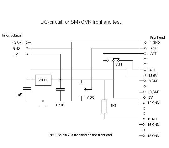
This results in this simple DC-schematic. The "missing" pins on the front end are found here. Please note that I have modified pin7, now with 13.6V!
In this simple manner it's possible to test a front-end as if it was mounted inside the FT225. I have tested several different configurations for AGC, NB and ATT in this way.
Comments
This test-jig is built with a double-sided Compar-connector and a big drawback is that one must be 100% sure, when a front-end is fitted, since there are voltages present on both sides! I think it's best to get a single-sided connector.
Here you can see another drawback, clearly not anything I thought of, but with a new front-end with surfacemounted components it's quite hard to do measurements, but the testjig can of course be upside-down...