


Introduction
I have owned my Hygain Tailtwister for some years and when I put up my new tower I thought that now is the time for some maintenance! The Tailtwister is an old relyable construction and if you turn of the power the direction-indicator doesn't keep indicating the direction of the antennas. This could be a disadvantage, but since a new rotator is quite expensive I decided to try maintaining it and hopefully this can be of some help for others also. I also hope that doing some maintenance will keep the Tailtwister from being a Fail-twister it's after all a very powerful and reliable rotator! I do not know how old my rotator is but the serial number is .
Dis assembly
There are six hex-bolts holding the bell together. If you have had your rotator in operation for some years and used stainless bolts you could have some problems now. My bolts were bad and I cracked two. Stainless steel and aluminium just wont cooperate!
When I lifted of the upper part the balls didn't fall out, but as pointed out by K4VUD - it's a good idea to open the rotator in a large tub or a bucket so if the balls fall out they are collected and don't end up all over the floor! There are plastic holders for all 138 stainless balls. Check for cracks in the plastic and replace if needed.
Be careful with the potentiometer on the inner-top of the rotator, this is probably the most sensitive part of the rotator.
Painting
Since I thought that the rotator looked bad I decided to paint it. I live about 10km from the sea and aluminium corrode quite a lot here.
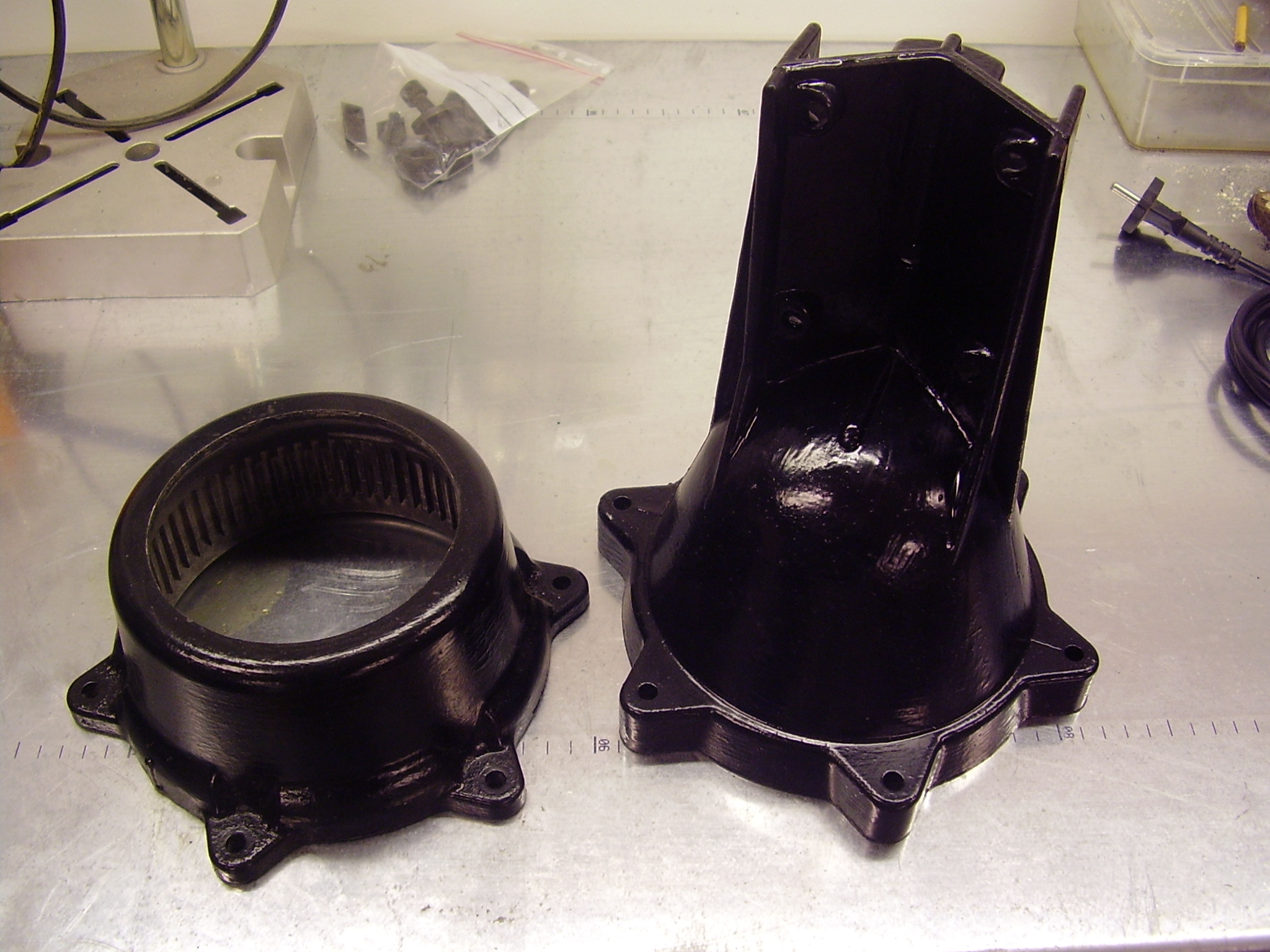
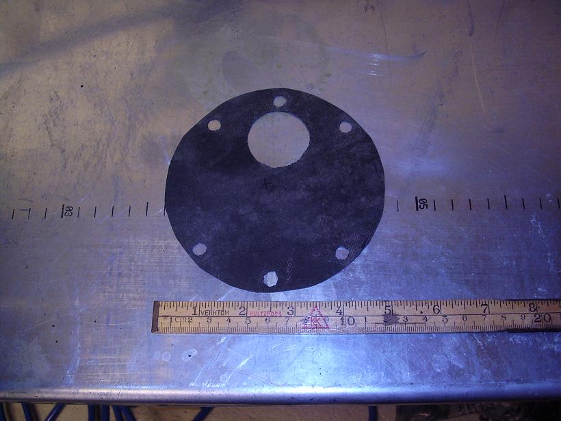
I began removing the most of the old paint, or what ever it is, with normal sandpaper. I don't think one have to remove all old paint. It's hard to paint aluminium with good results but an old man told me that he used the same type of paint that he used for outdoor wood so why not try this. The paint contain Alkyd-oil and the paint gets quite sticky, but flexible. (After a couple of weeks it's not sticky any longer.) I gave the rotator bell three layers of paint. You can see the result here. (There is 10mm between every black line on the bench so you can get an image about the size if you haven't seen this type of rotator before.)
The finish isn't something that you would have in your living room, but placed about 15m up there will be nobody seeing this...
If you would like to have an even better look you could try to anodize the bell, but I have not tested this. There would be several colours to choose from so this could be a funny thing to do!
Assembly
I changed nearly all of the balls to be on the safe side. After the change my ballbearings look like this.
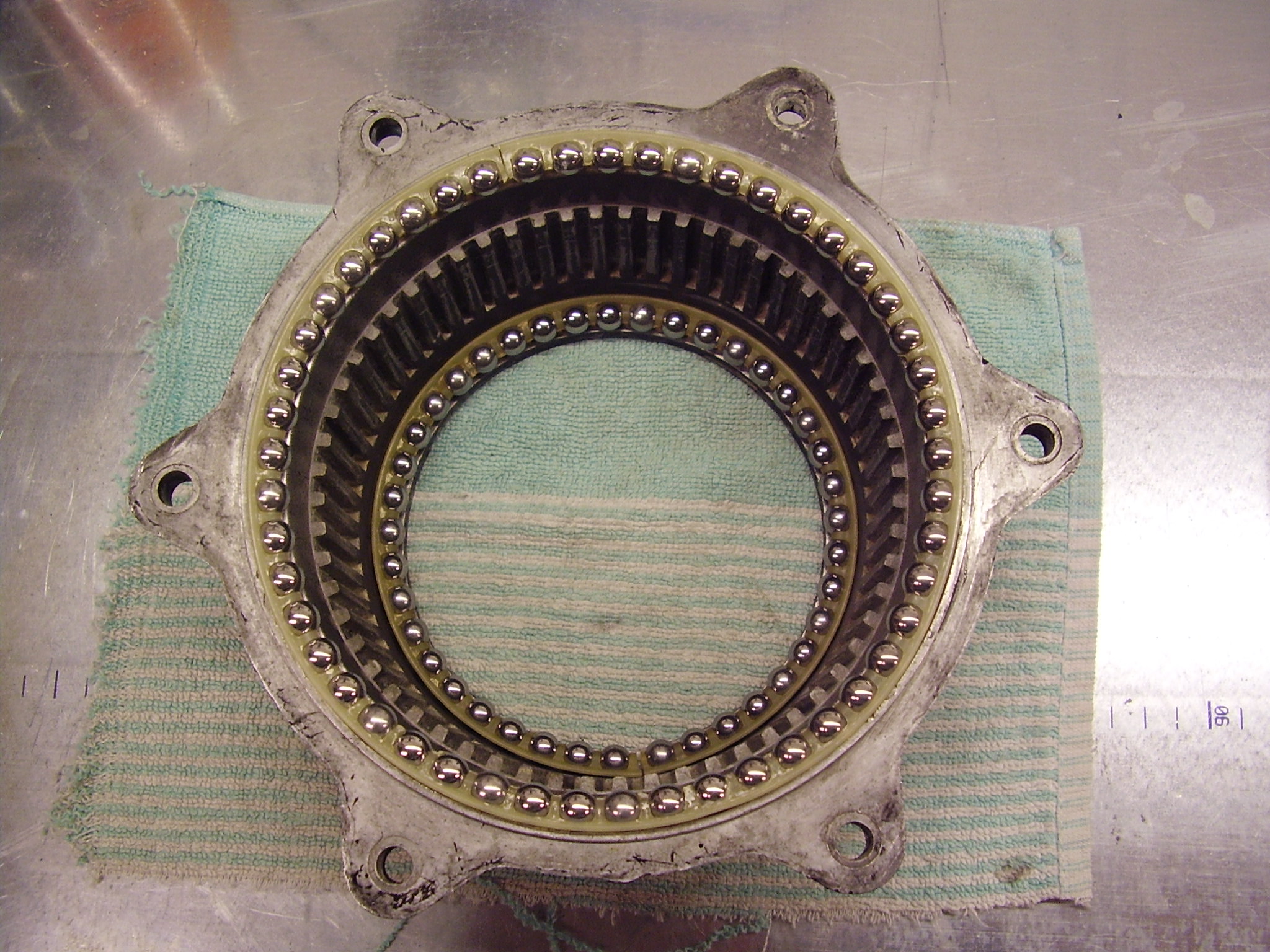
Here are the bearings placed in the lower part of the rotator. One can clearly see where the brake holds the rotator in the selected direction. I have not put any grease in the ball-bearings but it's made after the picture is taken.
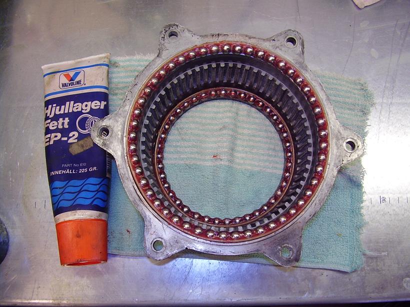
Do not use too much grease at least not if you live in cold areas. The grease can freeze and then your rotator will be stuck until it gets warmer! The grease I use is usable down to about minus 30 degrees Celsius. Its a grease from Valvoline normally used for cars, EP-2. Here are the bearings with grease. If you get to much grease in the bearings it will pour out downstream when hot. Now the lower part of the rotator is ready.
The upper part of the rotator is made in the same way. Here there is only one ballbearing. Put grease in this bearing but do not mount it inside the upper rotatorbell. It will be more easy to mount the rotator. Check the bottom of the upper rotatorbell. Here the potentiometer for the rotatorindicator will be connected. Check so there is no grease or dirt at this point.
The interior of the rotator should now be checked. Put a very small amount of grease on the moving parts of the break. (No grease on the electric parts!)
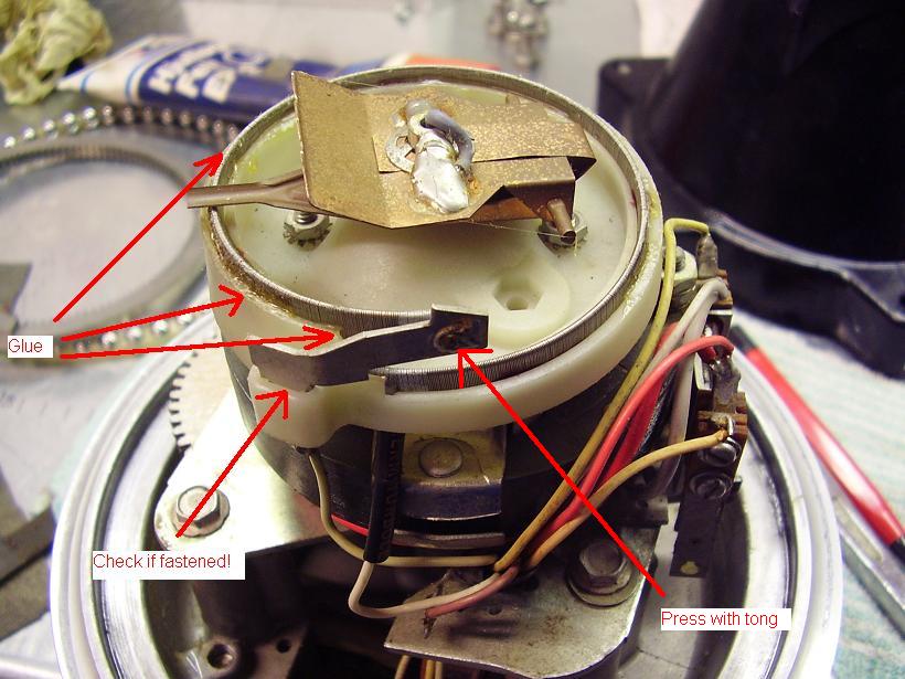
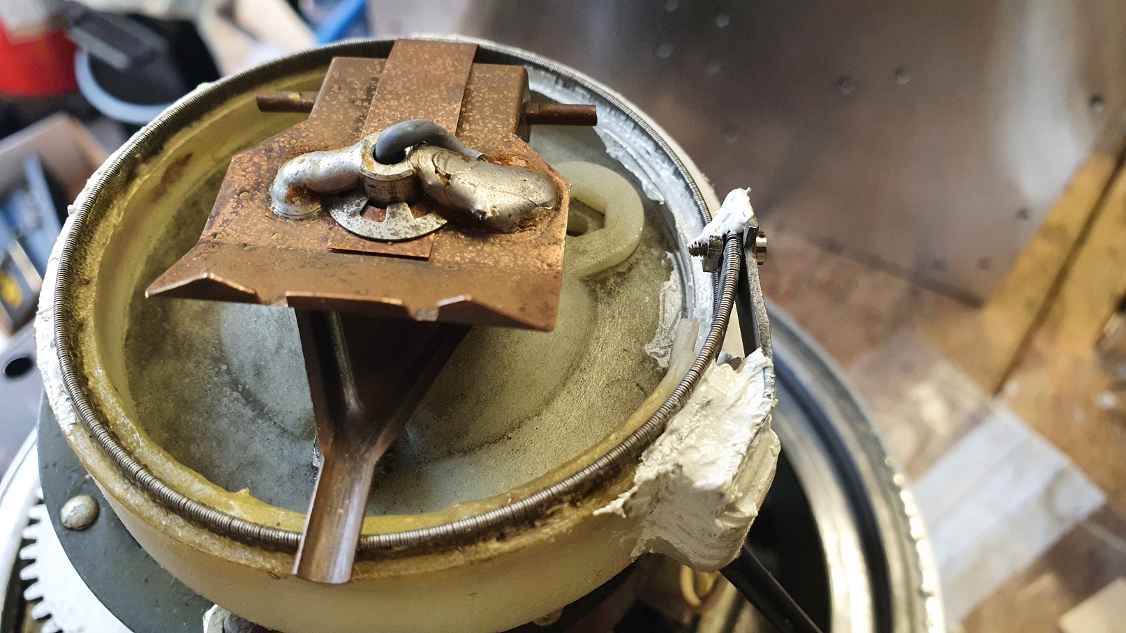
I have soldered a piece of cable, about a metre long, at the connections for the rotator. This cable is also shielded and I connected the shield to the housing of the rotator, close to the motor. Connect this cable to the control box. Check functionality of the rotator. The needle will not move, but more about this later. Your rotator should stop when it reaches the end-points. If you move the potentiometer on top with your fingers, careful not to get grease here, you will see the meter moving. Here you can see were I had problems. Suddenly the meter bumped and this is caused by the potentiometer moving. As you can see here I had to put glue holding the potentiometer tightly. Also check that the terminal showed is secured and do not move! When this is checked, press the rivet with a tong so you get a good connection to the potentiometer. Check again that you can move the potentiometer slowly without the meter bumping Run the rotator to one of its ends and let it be here. (Be sure that you have the ring mounted.) Turn the potentiometer to the same end.
I put the the lower part of the rotator, with its two ballbearings, on the vice and carefully put the interior into the lower rotator part. When the interior is in place check that it's resting on the vice.
Put the upper ballbearing in place. With some grease it will stick in place, at least to you have mounted the upper part of the rotator. With this package on the vice, look into the upper part of the rotator-bell and get it in right position and carefully slide it in place.
I would not recommend stainless screws since the rotator is made of some type of aluminium. I have used galvanized bolts, M8. When in place, begin with three bolts spread into the circle to see that everything matches.
Now you can test the rotator. The meter should move when you run the rotator. If not, you have not got the potentiometer right and you must open and check the interior!
If your rotator is working, put the last three bolts on. To be really sure I put an extra layer of paint on the bolts only. This will prevent moisture to get close to the aluminium and will prevent corrosion of the bolts. Hopefully your result will be like this or better.
Control box
Dangerous voltages are present inside the control box!
Since I decided to put a connector on the rotator cable, I have made the same thing on the control box. I didn't got any cable with eight wires left so I took eight single wires about one metre long.
I soldered the connector in one end and put cableshoes on all wires in the other end. It looks a little bit too simple, but since the cables are hanging behind my operating table I will not have to look at them every day and after all this is only indoors. If I get problems with the rotator later on I just take it down into the shack and then I can run the rotator directly without any difficulties as bad connections in the terminals.
It's important to check the large motor-capacitor inside the control box. If it looks bad exchange it. If you have very long wires between the control box and the rotator it might be a good idea to place the capacitor in some waterproof box up in the tower and connect the rotator to this other box.
If your cable is long it's also important to check to total resistance of the cable. The Tailtwister-manual clearly tells us, on page 11, that the cable resistance should not be higher than 0.8ohms for terminal 1 and 2. If you have higher resistance there is a risk that the solenoid will be noisy since it will not operate properly and you will hear a loud 50/60 Hz hum from the rotator.
The other cables can have slightly higher resistance, according to the manual 2.0ohms.
Terminal 1 is also ground, but the grounding wire inside the control-box is very thin. I have put a thick wire between terminal 1 and ground at the small transformer very close at the terminals. Also check that you have a grounded powercord, if not exhange it and put the grounding wire at the same point!
I have also put a VDR S10K60, (Elfa number 60-297-06), between terminal 1 and 2. This will prevent damages from overvoltages from the control-box or the other way... If your tower get stroked by lightning this could be very important! (I don't claim that this small VDR will protect your station but its an important part of your total grounding-system. More about the grounding-system is found here.)
What I didn't do is to exchange the power-on-switch. I should do this and maybe I fix this later on. The switch is originally only one pole and this is not good. You should always switch off both the neutral and phase, always!
Cable and connector
The cable I use from my shack up into the tower have several more wires than only the eight used by the rotator. The cable has 15 wires and the rotator only use 8. The idea is to have a box in the tower were other things as relay-control and other things also can be connected. If you have thin and long wires you might be forced to connect several wires in parallel, look at the manual for the rotator.
To be sure use a watertight connector. I found some nice 10-pole MIL-C-5015 connectors and these are very good for this purpose. Best is that when I get any trouble with the rotator I just take it down from the tower and can easily connect it to the control box.
Finish and mounting
Hopefully the rotator will be operating for several years now and this is how it look mounted in my new tower.
The plate were my rotator is mounted is made of stainless steel. It isn't good to mount any aluminium directly on this, and one should not use stainless bolts either! I cut out a rubber ring in thin rubber and cut six holes in it for the bolts and a larger for the connector. I bought normal 5/16 FZB-bolts and got copper-paste on them. Same type of paste used on cars on the break-details. More about the mounting and the tower is found here.
Update 2021
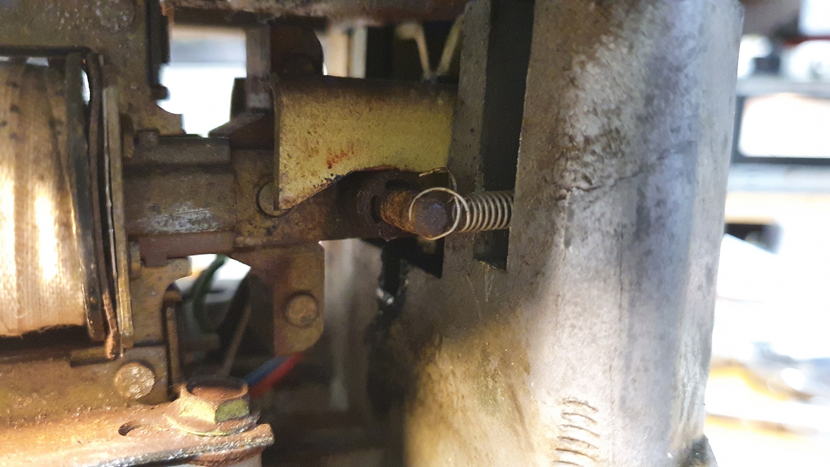
My indicator had problems from time to time and I also think that the brake was not always engaged, so I took it all down from the tower in September 2021.
The potentiometer for readout could move very little. This time I used epoxi glue, see picture. There are some wear and tear but it seems to work. Next time I may be forced to exchange this.