Introduction
I have made several measurements on my FT225RD and some are presented here. The reason is to make it easier for you to compare with your own FT225RD if you are troubleshooting or if you just want to know what I have achieved. I'm of course very interested to know if you come up with any solution that makes this transceiver even better! (Isn't that what Internet is all about-?)
I can't promise or guarantee that all FT225RDs will be the same and these measurements are made on my FT225RD with serial number 8E-050375.
Special thanks to Kenneth who let me use a FSH spectrum analyzer for many of these measurements!
IF-measurements with unmodified front-end
Here are some measurements made on the IF-output, ie between the RX RF-unit and the SSB IF-unit. The IF-output description is found at the IF-output pages.
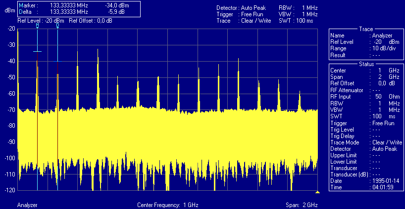
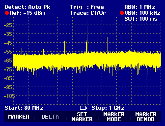
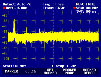
The output from the front-end is not clean as seen in this. The LO-signal is not filtered, or is shielded, and as can be seen, spurs are present up to 2GHz. This is not a problem if you are living on the countryside with no or very few disturbing signals around, but if you receive strange signal sit might be strong signals mixed with any of these spurs.
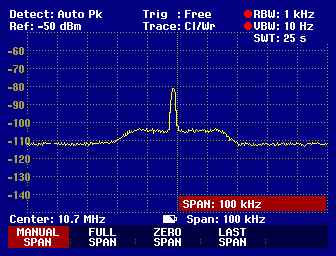
If we take a look at the 10,7MHz region it looks likethis. The signal near mid-band is the carrier to the product-detector at 10,6985MHz. This measurement is made with the antenna-input terminated with 50ohm. The measurement is made with the narrow filters available in the FSH and as can be seen the noise is only some 8 to 10dB above the noise-floor of the FSH. This measurement should be made with better equipment and I will get back to this.
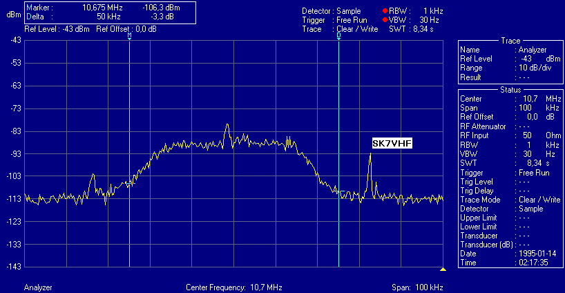
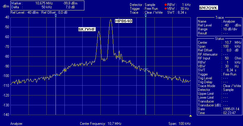
What is more important to notice is that the IF is poorly filtered! This first picture shows SK7VHF, (a beacon about 40km from my QTH), 33kHz away from the center! It's also clear that the IF-bandwidth is above 50kHz, look at the distance between the M and D ie Marker and Delta! This is ok if the receiver could handle strong signals, but it can't originally. This is one of the reasons why you have lots of signals around at contests, another reason is that to many stations are badly filtered.
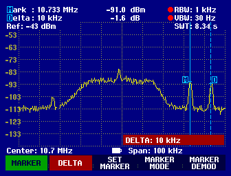
To show this more clearly I put a signal generator, an old HP8640B, 43kHz from the center together with SK7VHF. The signalgenerator is coupled into the receiver and the output adjusted to be as strong as SK7VHF. (Interestingly no intermodulation-products can be seen, but this probably since the signals are so weak compared to the noisefloor.)
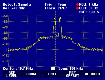
With the center frequency changed in order to get both signals inband, this is the result. The output-power from the signalgenerator is the same as earlier, and this show that the noisefloor of the spectrum analyser is much higher than the FT225 since we can't see how the filter-characteristic looks like on the filtersides.
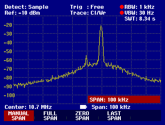
With the generator decreased the spectra looks like this and if the generator-power is increased the AGC does what it can to lower the receiver gain.
Transverter output
The transverter output as described on the RX/TX split-page is also measured. The output is filtered originally in the FT225RD, the schematic is here. The filter is simple but appropriate for most transverter designs, but it's important to know how effective the filtering is since different transverter designs could need special filtering. Phase-noise is very important to keep as low as possible! There are several reasons for this, but one important reason is that we don't like any strange signals entering the mixer since this will develop new signals at IF. This mechanism appears when there are spurs in the local-oscillator signal. It could also be the noise surrounding the carrier that will hide a very weak received signal. Everything that comes from the local-oscillator will mix with the received signal. It is therefore also important to have some type of filter on at least the received signal but it's a good idea also filtering the LO. This will keep out of band signals from being mixed down to IF.
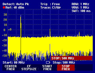
When the transceiver is in receive-mode the output looks like this. In transmit the output changes, naturally, to this in USB-mode. The signal that can be seen here is the carrier unbalance, but it's quite weak and temperature dependant. I haven't found out if it's possible to make this insensitive to temperature changes.
When the transceiver is changed to transmit-mode, CW, the spectra looks like Phase-noise
There are special instruments to measure phase-noise. I don't have access to any, but it's also possible with some spectrum-analysers and the FSEA from R&S does this nicely with a special software in an attached computer.
Home