
Beginning
Modes that yesterday needed sophisticated modems are possible today with an ordinary computer equipped with a soundcard. We have probably just seen the beginning of this "era", and there will be new modes and accessories to follow. Some brief things about WSJT and meteorscatter are found here.
These software-types are often available as shareware or freeware on the Internet.
WSJT and PSK31 are two of these software-types. (These links are only two examples and I think the best way is to make a search on Google, or another search-engine.)
These software-types are using the RS232 to control the PTT and two things are important when building the interface;
- isolation between the radio and the computer
- the switch must be able to handle the current needed
On the FT225 the PTT is a closure to ground. The "positive terminal" on the PTT-relay is constantly fed with +13.8VDC and when PTT is pressed the other relay-terminal is grounded. The switch must be able to handle the current needed by the PTT-relay and this is about 130mA. A normal opto-coupler can't handle this high current.
The circuit
The PTT-relay is using about 130mA and the best way is to use an extra transistor. I thought that the easiest way is to use a PNP-transistor since I didn't want any extra power-supply for the switch circuit, (many solutions found on the net need an extra power-supply for the switch). In this way it is possible to build the circuit into the D-sub connector.
I used a BD136 and this PNP-transistor can handle 1A, but there are hundreds of PNP-transistors to choose from and it is really not critical. Try to find a type that can handle at least 250mA to be on the safe side!
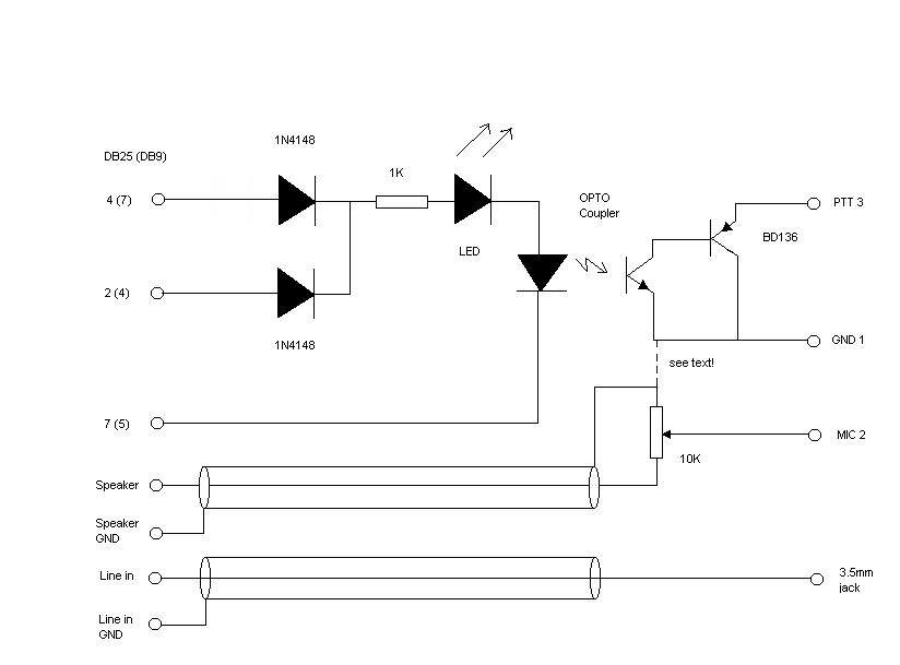
You find the schematics here. The pin-numbers in brackets are pin-numbers for the 9-pin D-sub connector. I used a 25-pin D-sub since there are more room for the components and I also have a switch with four inputs and these are all 25-pin.
The numbers after MIC, PTT and GND on the right side of the schematics are the pins in the FT225 MIC-connector.
The dotted line from the GND to speaker-GND is important. If you use a stationary PC and the AC-sockets are grounded, and really connected to ground, you should not connect this! It depends also how the FT225 is grounded. You might create a ground-current-loop. If you get any hum try to disconnect! If you are using a portable PC this might not be grounded and then you have to connect! The idea with ground-connections in LF-systems is that the grounding should be made in one single point.
The potentiometer value is not critical, 10-47K will work and will be simple to adjust.
Mechanics
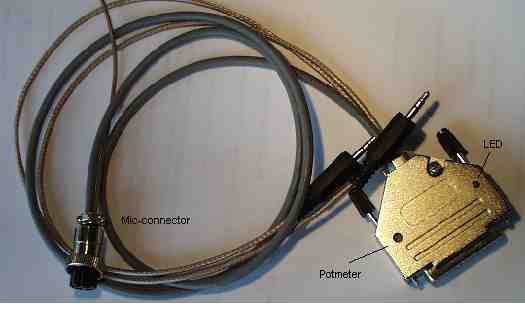
I used a 3mm red standard LED. I also drilled a hole in the D-sub connector for the potentiometer. The LED-hole is drilled with a 3mm drill and the LED is glued with "super-glue". The potentiometer-hole is about 4mm and the potentiometer is also glued in place.
The cables to the soundcard go into the 25-pin D-sub. Out from the FT225 mic-connector there is a short cable to the phones-jack.
You can see the result on these pictures, outside and inside.