Background
Some time after I put the first version of the "CW-filter" into the FT225 I began looking on the original BP-filter.
After some "reverse engineering" I got convinced that the constructor originally had in mind to use a 3-pole filter, but only a 2-pole filter was put in the FT225.
The filter is placed in the SSB-IF-unit, PB1778, between Q05 and Q06. If I am right then it should have been a standard 3-pole UG-type, UG for "Unity Gain".
If I calculate the components for a 3-pole Butterworth-filter with a 3dB-break point at 3kHz, I get nearly exact the values used! The only difference is that the last RC-link for the third pole is missing!
First test with an extra RC-link
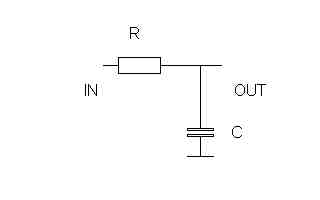
Since I had made the calculations for a 3-pole filter according to the already used components I first tried to add the "missing" RC-link. I got the values 5K1 for the resistor and 10nF for the capacitor. (Calculation example further down this page, to clarify any doubts - schematics with the later used labels is found here.)Results
Subjectively, I really think this extra RC-link really gives effect! The simple "CW-filter" is not loaded in the same way so this extra filter also works much better!I didn't have any audio-instrument to measure the filter-bandwidth. The easiest way to get a hint about the filter-bandwidth is to record received noise with a soundcard. I used software, made by OK1FIG, to graphically show the intensity on the frequencies of interest.
Calculation of a new 3-pole UG-filter
Specification
It is always important to have a goal, so before we can calculate any filter components we must know the wanted specifications.- Butterworth
- 3dB point at 2.5kHz, ie fg=2.5kHz
- More than 30dB attenuation at 3*fg
Number of poles
The specification "Butterworth" and "3* fg" inform us that we have to use a filter with 3 poles.The UG-filter
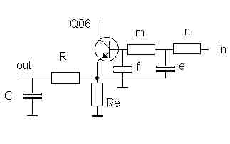
Schematics on the UG-filter is found here and the labels later used are the same as in this schematics. There are three capacitors and three resistors to be calculated. This calculation is made in a standard procedure.The angular frequency is calculated as;
w=2*pi*f
with f=2500Hz, we get w=15708 rad/s.
This angular frequency is used to denormalize some different factors, I will not point out the function of these factors and you could find this described in several different books. The factors might be called something else, but the result will be the same.
Butterworth
Since I have chosen a Butterworh-filter the normalized factors Sp and wop will be for the first, and the only single pole;Sp=1 and wop=not defined
For the other two poles, the normalized factors are;
Sp=0.5 and wop=1
Calculation of the RC-link
The RC-link, or the first pole, is calculated by denormalizing the Sp;Sp = 1*15708 = 15708 = 1/(R*C)
This gives us, with the same R as before, 3900ohms;
C = 1/(R*Sp) = 1/(3900*15708) = 16.3nF
This is not a standard value, we therefore change the C-value to a standard value, ie C=10nF. The R is then;
R = 1/(C*Sp) = 1/(10-9*15708) = 6366 ohms
The closest standard value is 6340 ohms.
Calculation of the other components
The resistors n and m are chosen to 3900 ohms, since this value already has been used. This gives us the e and f; e = 1/(m* Sp) = 1/(3900*0.5*7854) = 33nFf = e/4 = 33/4 = 8.2nF